XMAMan.PhysicEngine.GrxExtension
0.0.2
dotnet add package XMAMan.PhysicEngine.GrxExtension --version 0.0.2
NuGet\Install-Package XMAMan.PhysicEngine.GrxExtension -Version 0.0.2
<PackageReference Include="XMAMan.PhysicEngine.GrxExtension" Version="0.0.2" />
<PackageVersion Include="XMAMan.PhysicEngine.GrxExtension" Version="0.0.2" />
<PackageReference Include="XMAMan.PhysicEngine.GrxExtension" />
paket add XMAMan.PhysicEngine.GrxExtension --version 0.0.2
#r "nuget: XMAMan.PhysicEngine.GrxExtension, 0.0.2"
#addin nuget:?package=XMAMan.PhysicEngine.GrxExtension&version=0.0.2
#tool nuget:?package=XMAMan.PhysicEngine.GrxExtension&version=0.0.2
PhysicEngine-Examples
The XMAMan.PhysicEngine-NuGet-Package can be used for the simulation of 2D-rigid bodys. This means, if you want to simulate the movement from a car, bridge, skijumper or any other object that is somewhat solid, then this NuGet can you help. This package supports at the moment no fluid-physics or softbody-physics.
There are two packages available:
- XMAMan.PhysicEngine → its only for the physics calculation
- XMAMan.PhysicEngine.GrxExtension → extends the physics engine with graphical output (intern OpenTK is used)
This usecase are shown here:
- Case 1: A stick which can jump
- shows how to create a object with multiple joints and how to move all joints with a single animation
- shows how to handle collision-events
- use XMAMan.PhysicEngine.GrxExtension-NuGet for graphic output
- Case 2: A gripper
- shows how to use multipe animations for a single object
- shows how to use WPF for graphic output
To use this NuGet-Package, you need the leveleditor where you define your physicmodels from your objects. This editor can be found here: Leveleditor.exe
This editor is needet for creating *.txt-files (content is a json-string), which can be used by the XMAMan.PhysicEngine-NuGet-Package for simulating the movement from 2D-solid-objects.
Exampleproject 1 - JumpingStick
Step 1.1 - Define the levelfile "StickPlant.txt"
In this project we want to simulate a stick which is able to move. To do this we need at first a description of the stick and its environment. This description is created by the Leveleditor.exe
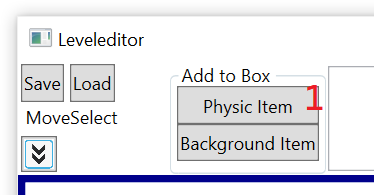
So start the leveleditor and click on "Physic Item" (1) to open the editor, where you can define a single physic-object.
In our case we want to define a stick, which is able to move. To do so, click on "Add Rectangle" (2) and then left-click in the white area and move the mouse and left click again to define the first rectangle.
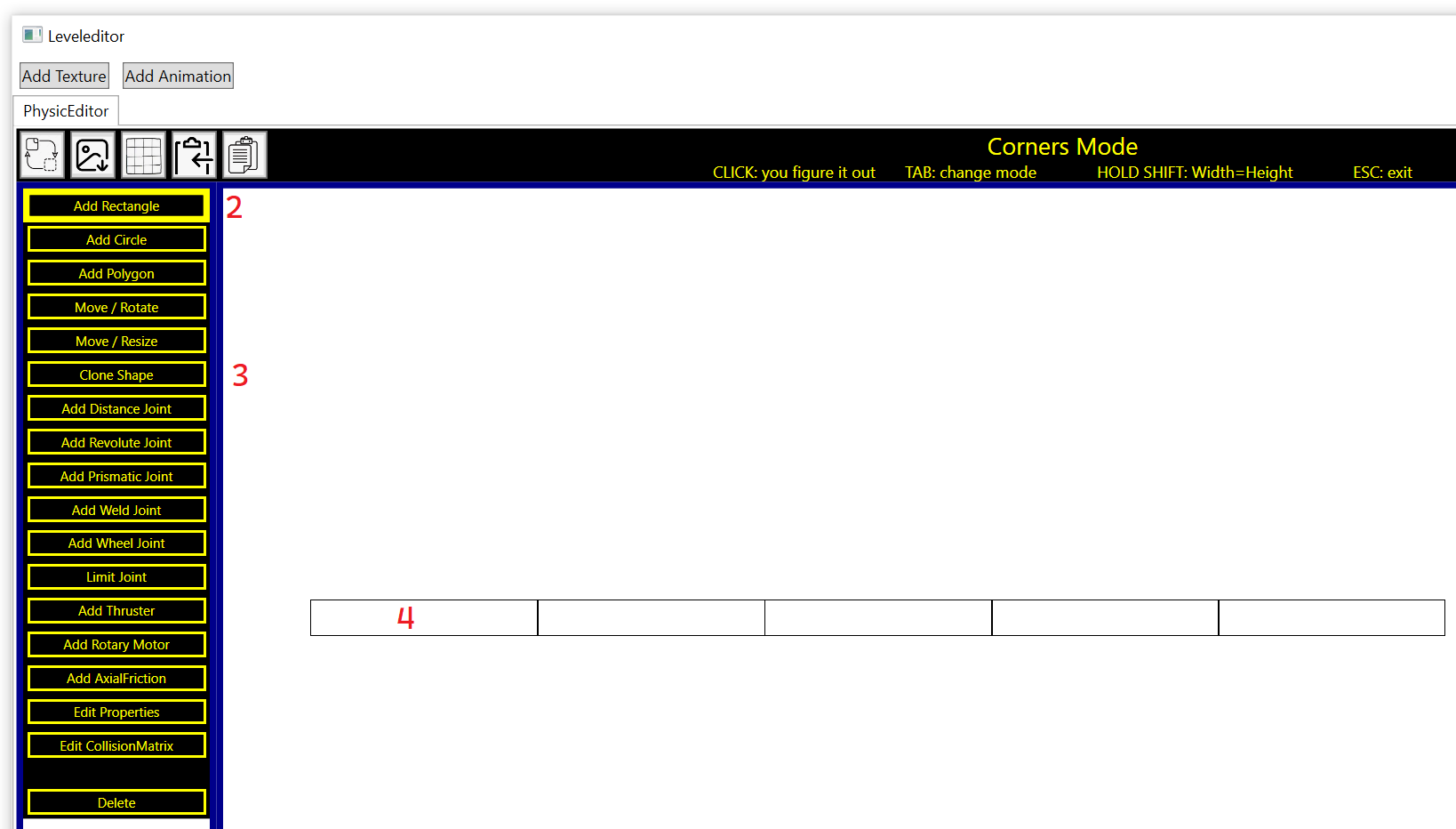
After the creation of the first rectangle we want to copy this and move the copy only in X-direction. To do so click on "Clone Shape" (3) and after that left click on the rectangle (4). Hold the shift-key and move the mouse in right direction. This will create a second rectangle which you can place beside the first rectangle. Repeat this cloning-step for the other rectangles so we have 5 rectangles in row.
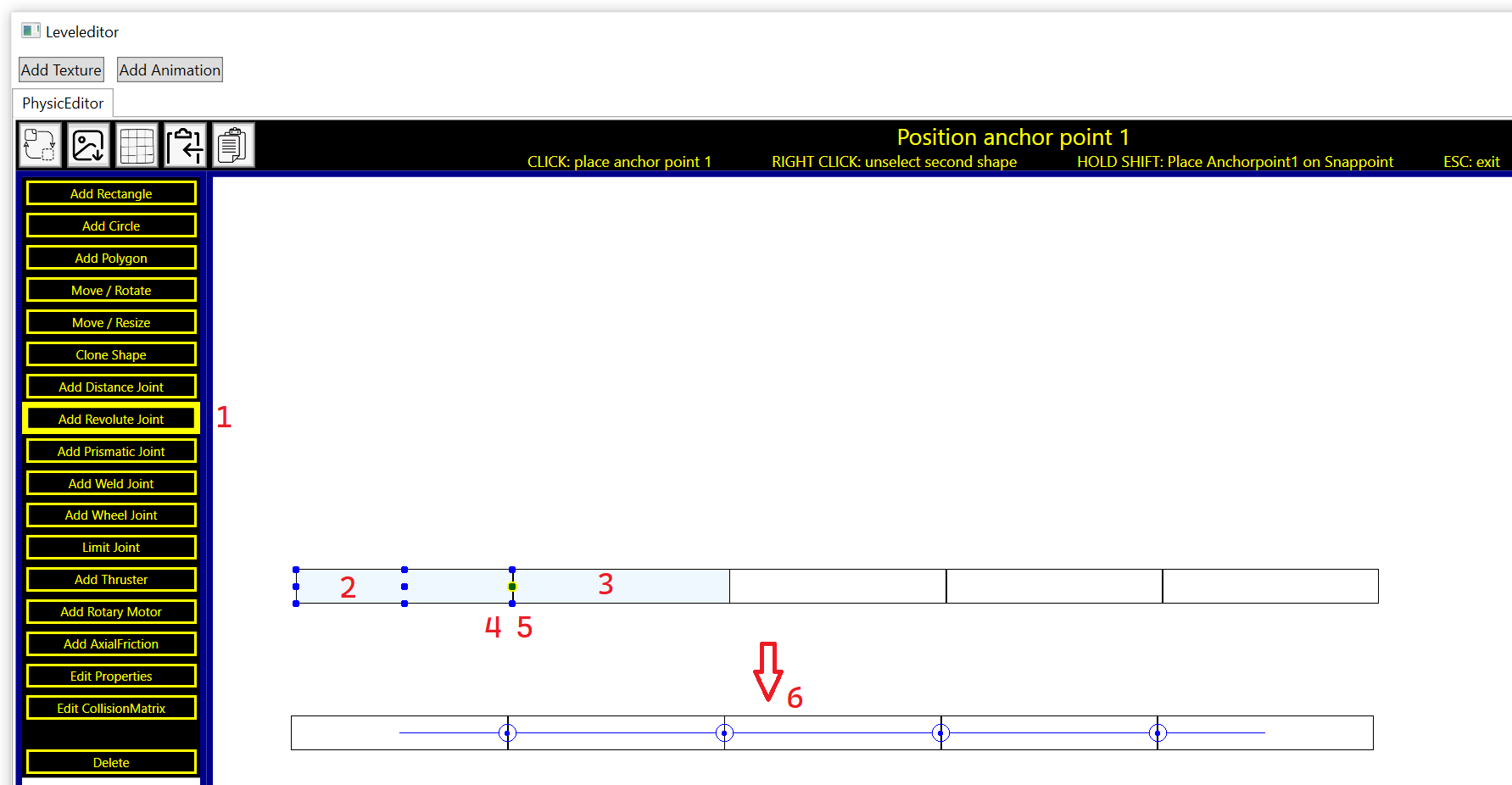
We now need connections between the rectangles. We are using the revolute-joint for this. Click on "Add Revolute Joint" (1) and then on the first rectangle (2). Then click on the second rectangle (3). Hold now the shift-key which will show the blue anchor-points. Click on the point on the right side from rectangle1 (4) and then on the point from the left side from rectangle2 (5). This will bind the points (4) and (5) together. Repeat this step for all other rectangles to bind all segments together. If you are done then your physic model should look like the this (6).
The next step is to define the moving range from the revolute joints. Click on "Limit Joint" (1) and then on the first revolute joint. You can now move the min- and max-limit-arm (2) and (3) by holding the left mouse down and move it. The yellow circle segment shows the allowed range from the right green lever arm with index 2.
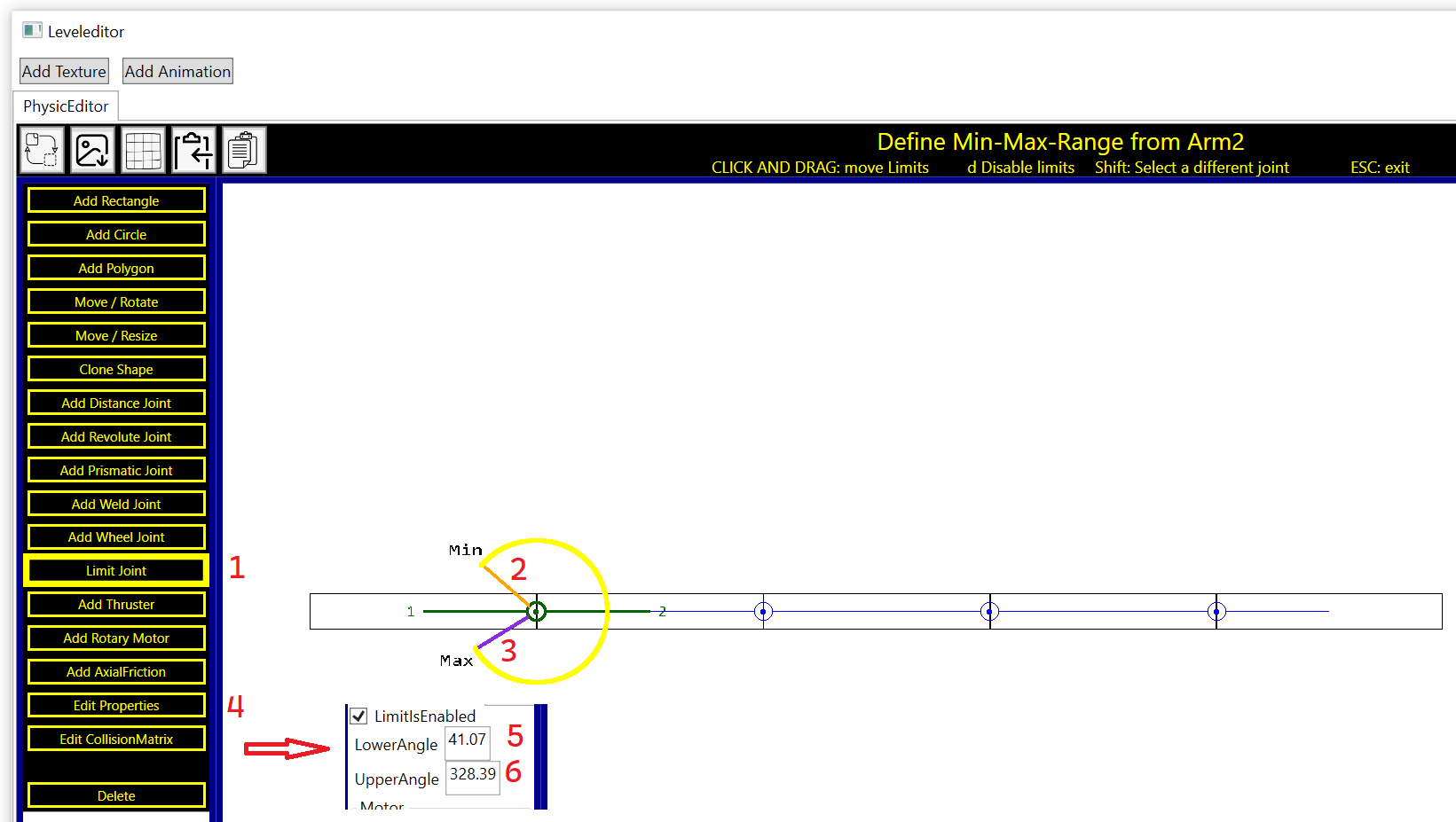
Click now on "Edit Properties" (4) on the menue bar and then hold the shift-key and left-click on the first revolute joint. You can now see the lower (5) and upper (6) angle from the joint. If you want to use for all joints the same moving-range then use for all joints by example 20 degree for the lower angle and 340 degree for the upper angle. Use the Edit-Properties-function to set for all joints the same limit-values.
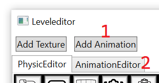
We now want to control all revolute-joints so that the stick is able to move. To do so click on "Add Animation" (1) on the left top side and then on "AnimaitonEditor" (2).
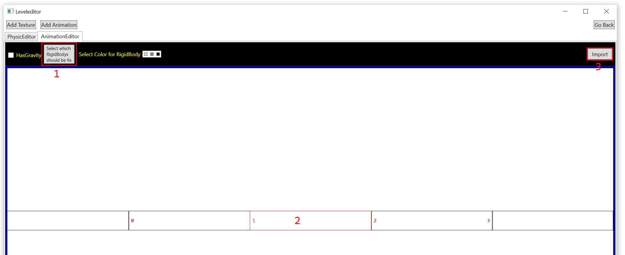
In the next window click on "Select which RigidBodys should be fix" (1) and then on the rectangle in the middle (2). This step is needed otherwise the stick will float around durring the definition of the animation-step.
Right-Click now on the yellow area on the left top corner (1) to create a new key-frame. Move the created key-frame to the left side (2) by holding the left mouse. Create a second key frame by right-clicking again in the yellow area (1) and then move the frame to the right side (3). The key-frame with the red border is the currently selected frame. In this image is the left key frame (2) selected and for this frame you see on the right side the values from alle joints (4). Move all sliders a little bit to the left so that the stick looks like in in image.
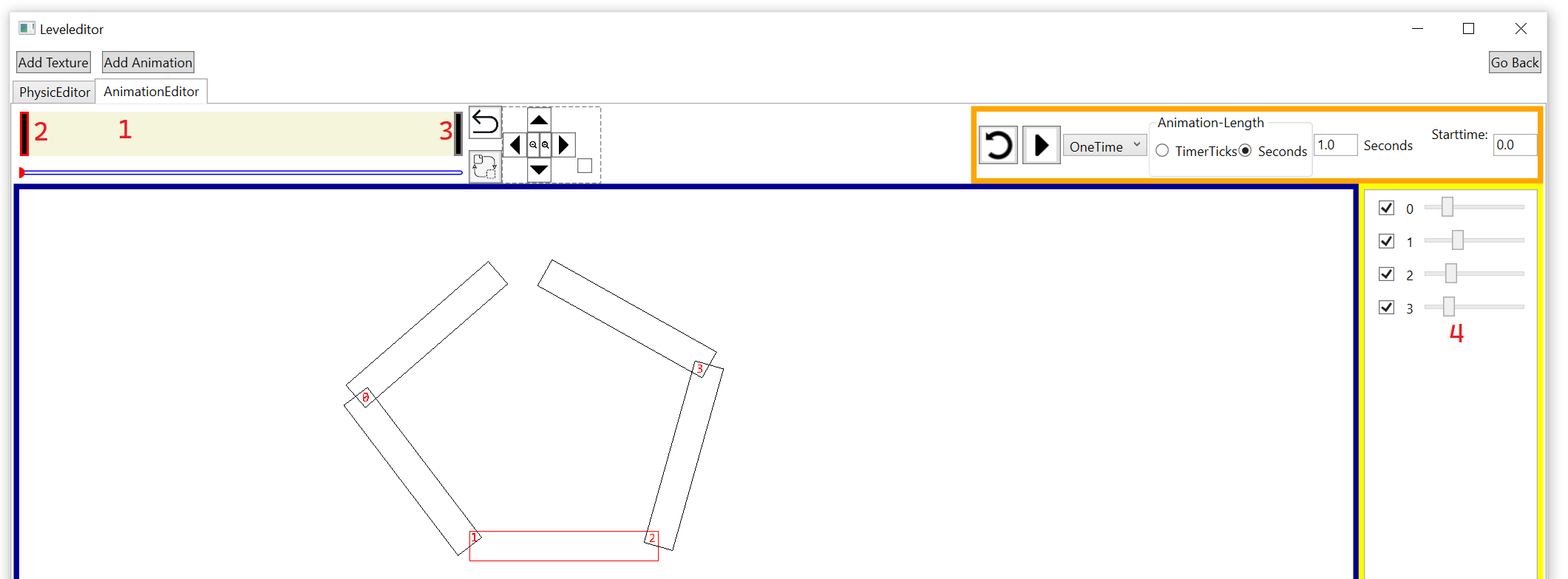
Select now the second key frame on the right side by left-clicking on the rectangle (1) and then move the sliders a little bit to the right side (2) so that the stick looks like in the image:
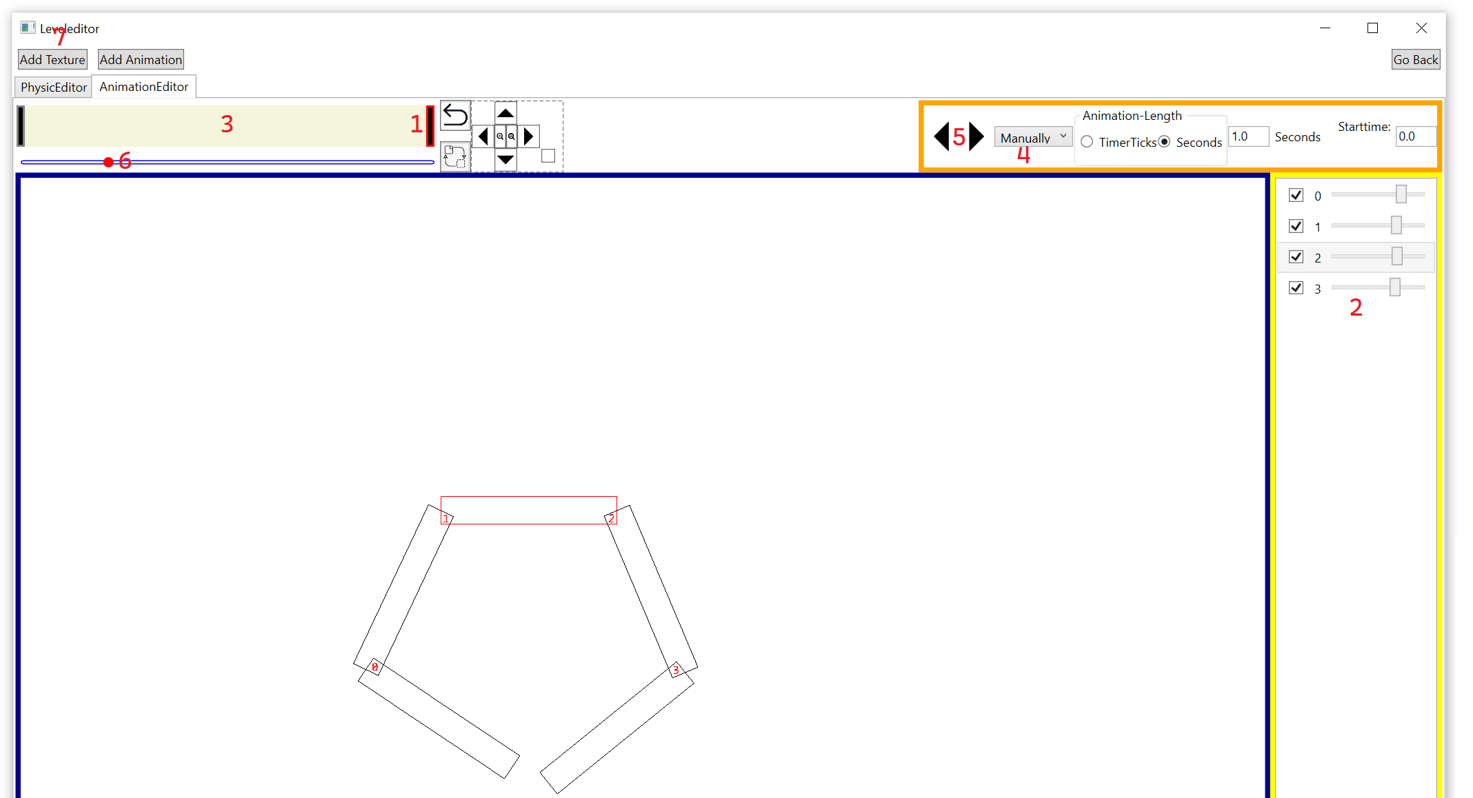
Left-click in the yellow area (3) to deselect all key-frames. Select in the combobox (4) that you want to use a manually animation und then hold the forward/backward-buttons (5) the see the animation. The red circle (6) shows the animation-position.
This animation now defines the movement from the stick. Click now in the "Add Texture"-Button (7) on the left top side to create the TextureEditor-Tab.
To open this tab click on (1) and then on the first rectangle (2) so select it. We want to use a texture for this rectangle so click on the "..."-Button (3) and select the "Circles.png"-image from the data-folder from this project here. Set "MakeFirstPixelTransparent" to false (4) to show the hole image.
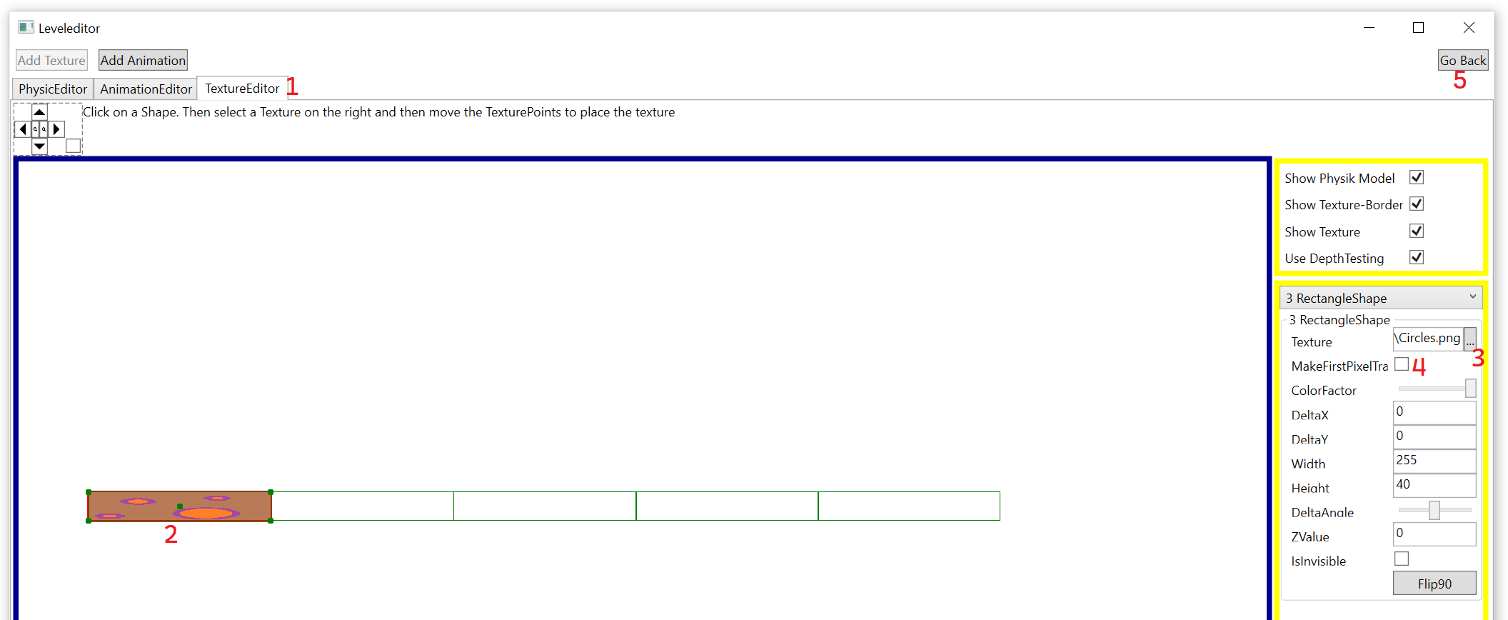
Do this for all rectangles. If you are done click on "Go Back"-Button (5).
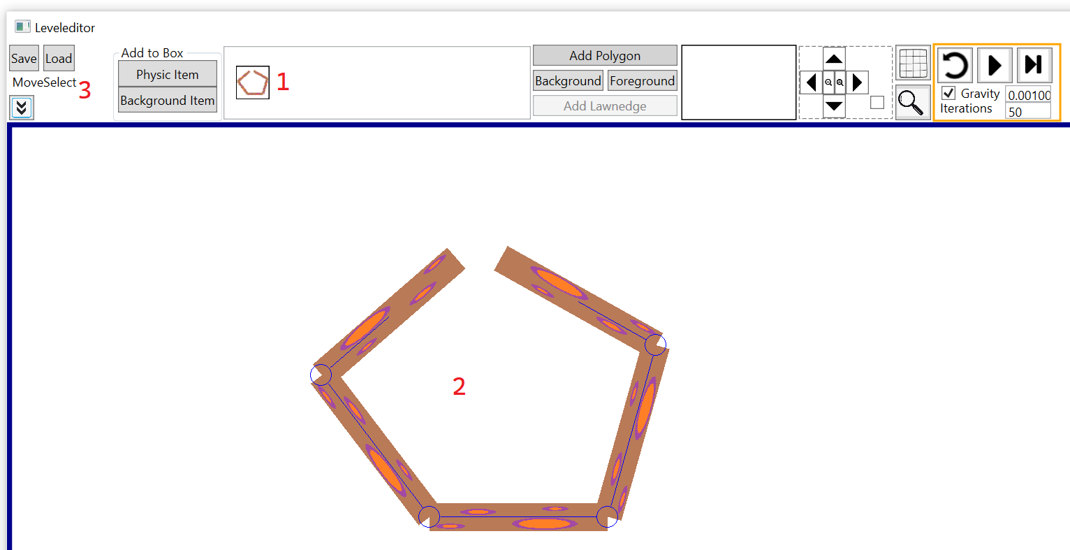
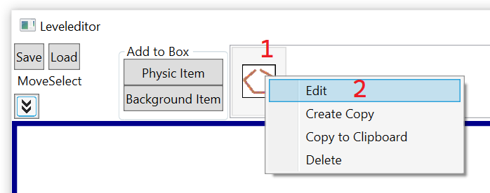
You see now that the stick appears in the item-bar (1). Left click on the stick and then move the mouse in the white area and left-click on it (2). After that press the escape-key to leave the editor from the AddItem-state and go back to the MoveSelect-state (3). The initial-position from the stick is at the moment the left key frame. We now want, that the middle from the animation is used. To do so right-click on the stick from the item-bar (1) and then click on "Edit" (2).
Select the AnimationEditor (1) and use 0.5 as starttime (2) for the animation. Click on "Go Back" (3).
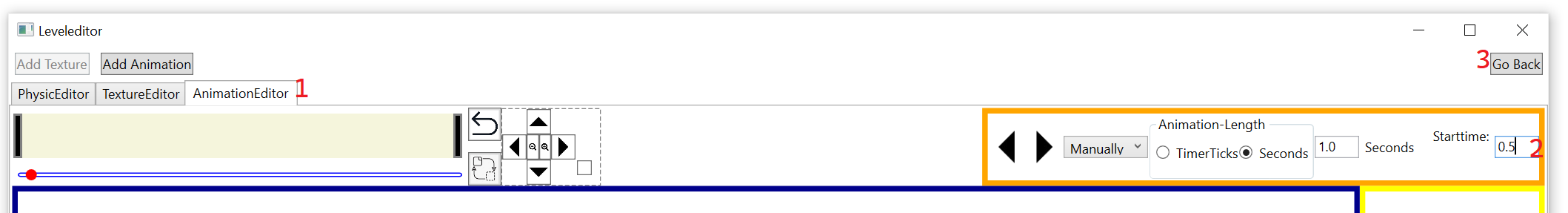
You can see the change in the item-bar (1). The stick starts now more in a straight position.
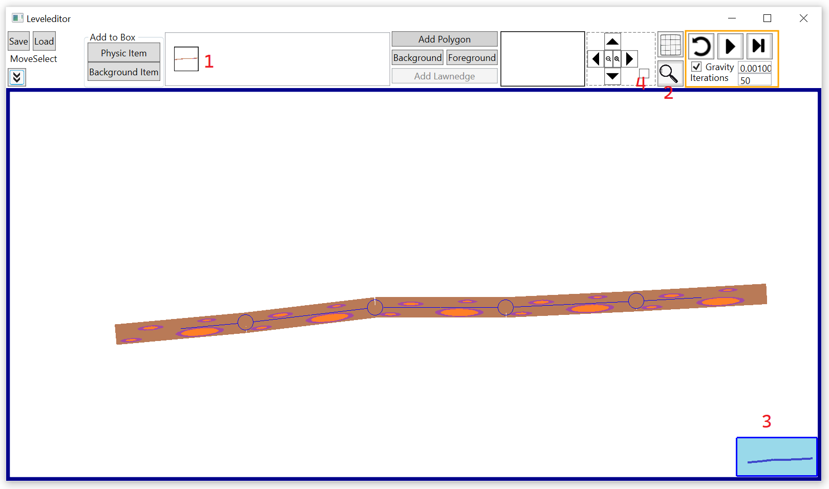
We now want to create the ground. To do so we need to zoom out. Click on the magnifying glass (2) and you see now a little window at the right bottom corner (3). Click at next on the auto-zoom-check-box (4) which will add a yellow rectangle to the small windows at the right bottom edge.
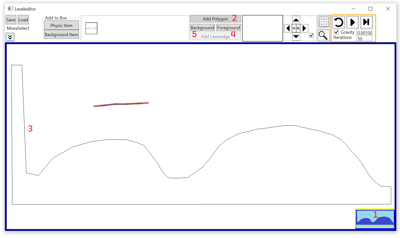
Place the mouse inside from the yellow rectange (1) and use the scroll-wheel for zooming out. Hold the left mouse button inside the yellow rectangle and move the mouse together with the rectangle to change the camera-position. Click now on the "Add Polygon"-Button (2) and create the ground-polygon (3). After that click on the "Foreground"-Button (4) and select the stone.jpg-texture for the ground. For the background we want to use the sky.png-texture. Select this image with the "Background"-Button (5).
The editor looks now like this:
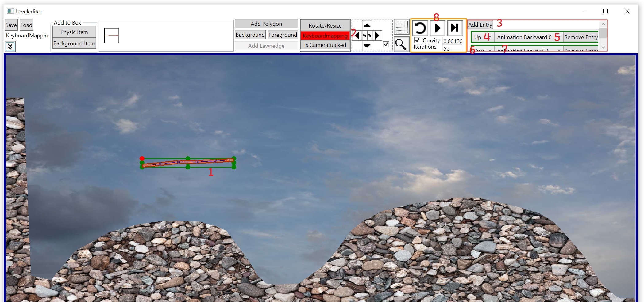
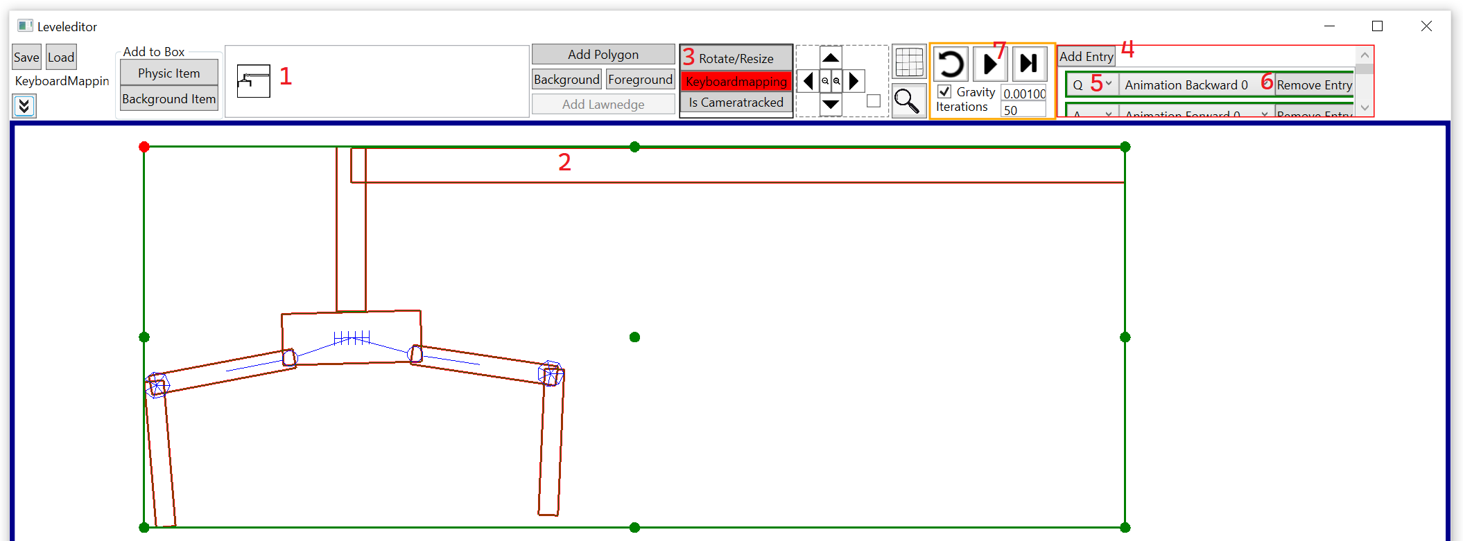
We now want to define the keyboardmapping for the stick. Leftclick on the stick (1) and then click on "Keyboardmapping" (2) and on "Add Entry" (3). To move the animation backwards we want to use the up-key. So select this key in the combobox (4) and select in the combobox beside "Animation Backward 0". Click again on "Add Entry" (3) and use for the forward-animation (7) the down-key (6).
You can test now the movement from the stick by clicking on the simulation-button (8). You will now see, that the stick is falling down and if you hold the up/down-key then the stick is moving. If you press the esc-key then you go back to the editor-view.
For the ground-polygon we now want to add some lawn. To do so select the polygon by left-clicking it (1) and then click on "Add Lawnedge" (2). Click on the edge from the polygon on position (3) to define the start-position and then on position (4). Click on the "..."-Button (5) and select the Lawn.png-image and then increase the lawn-height to 80 (6).
Do this also the other hill. Your editor looks now like this:
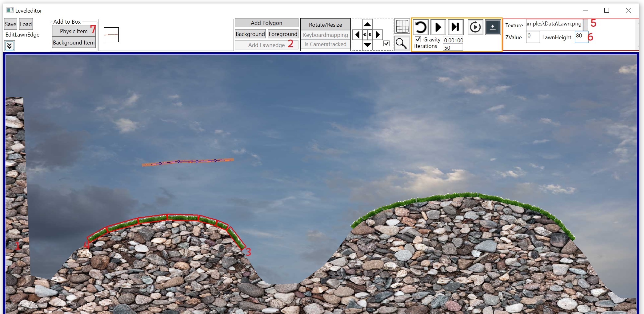
We also want to add a stone-man standing on the right hill. To do so click on the "Physic Item"-Button (7).
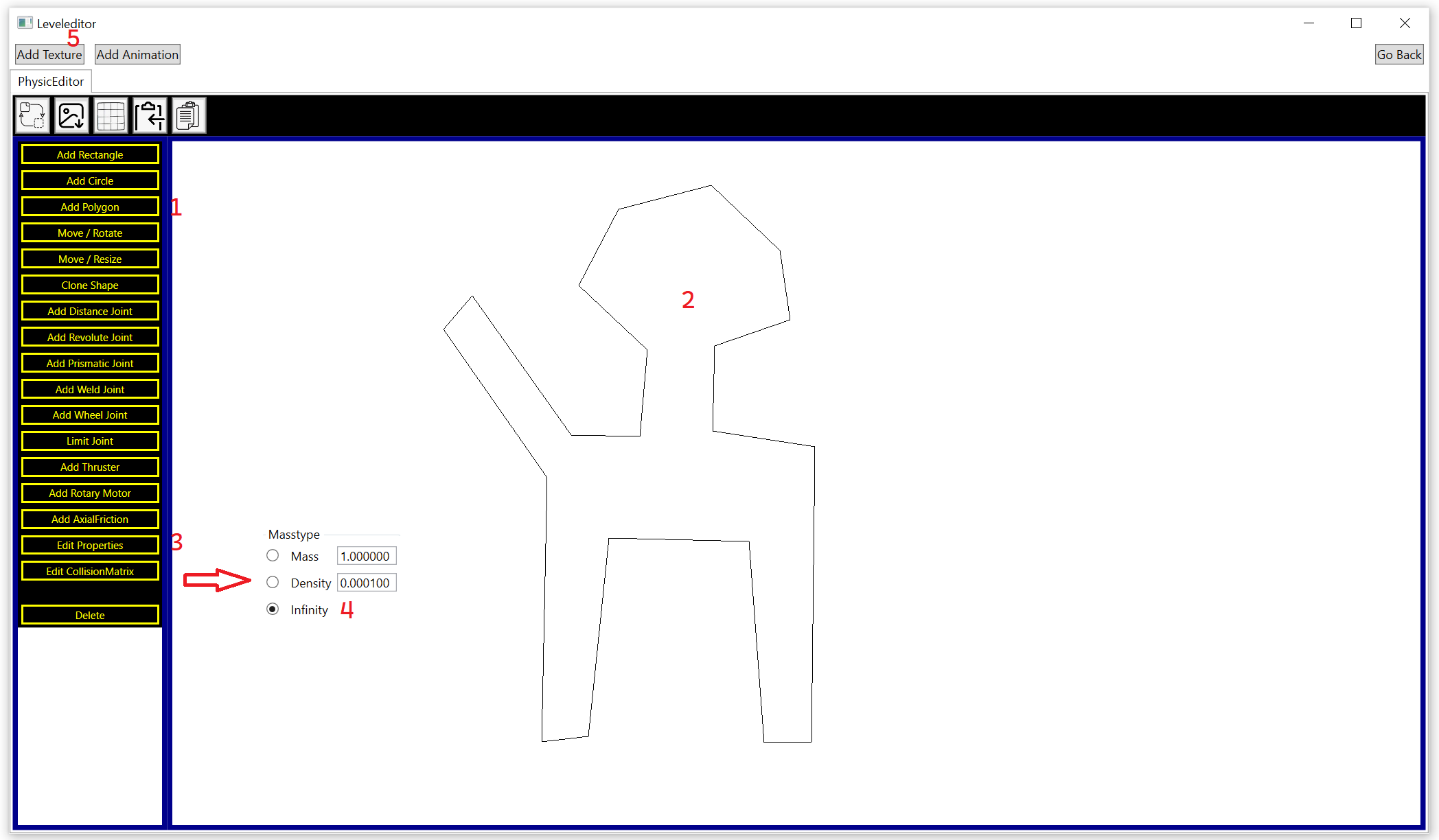
Click on "Add Polygon" (1) and define the man (2). The man should be a stone so it can not be moved (so easy). Click on "Edit Properties" (3) and then on the polygon (2) and use Infinity (4) as masstype. This polygon will now stand fix on a position. Click on "Add Texture" (5).
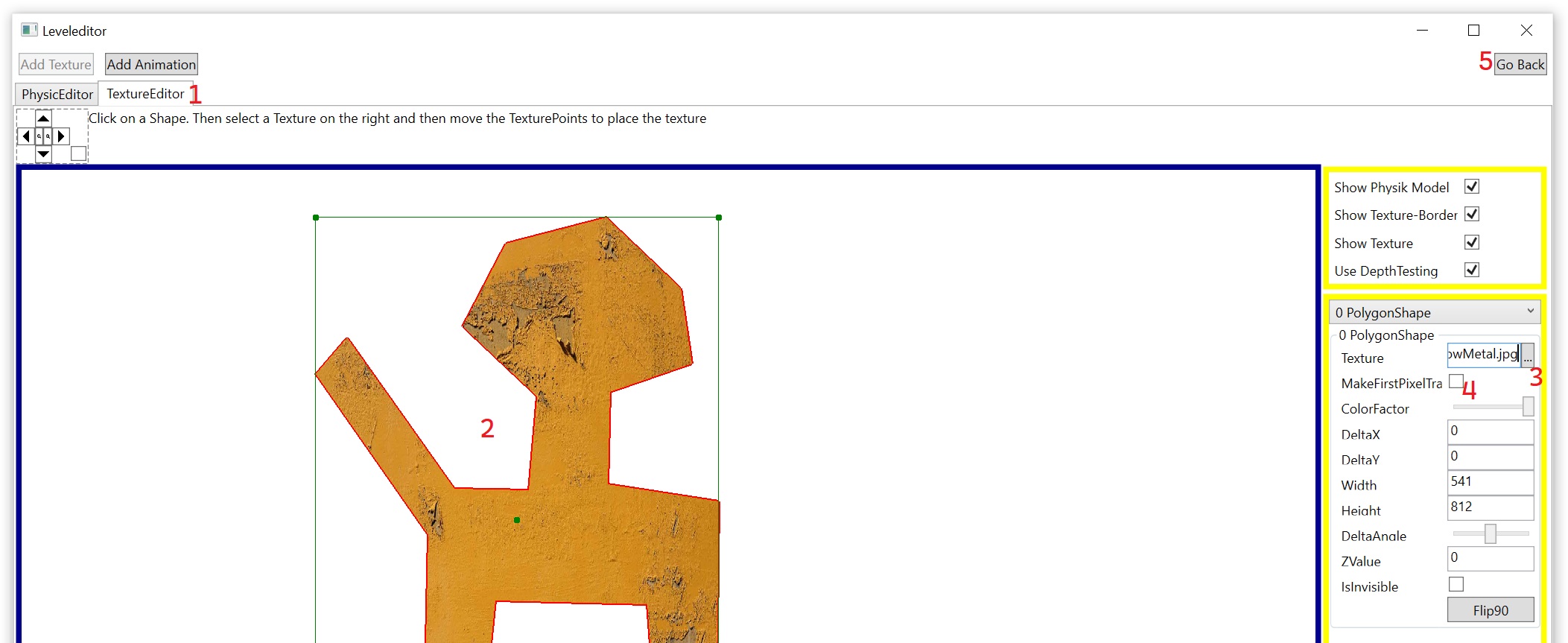
Select the TextureEditor (1) and then click on the polygon (2) and select the yellowMetal.jpg-image (3) for the polygon. We don't need a transpararent color (4). After that go back to the main-editor (5).
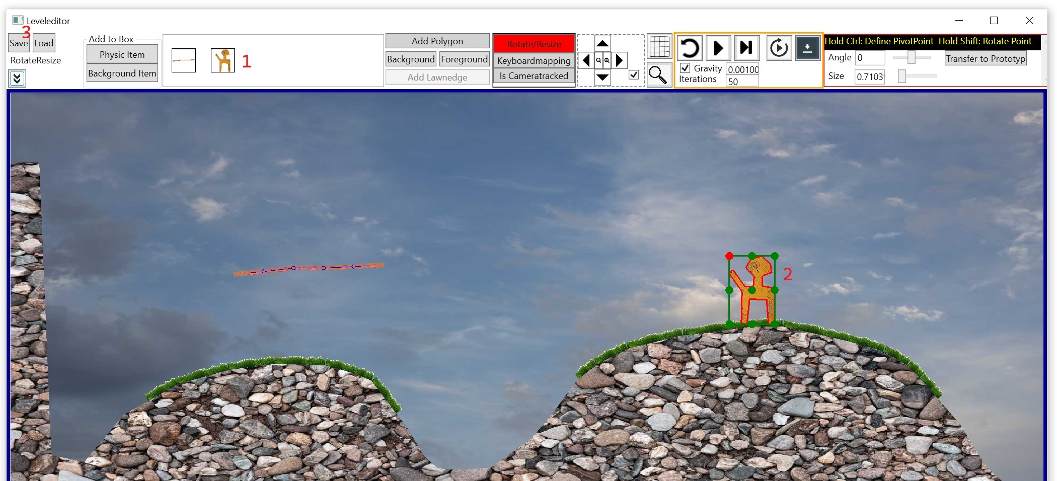
Select the stone-man in the item-bar (1) and place it on the right hill (2). Left-click on of his green corner-points and move the mouse the scale the size from the man a little bit down. You can now save the levelfile with the "Save"-Button (3) under the name "StickPlant.txt".
Step 1.2 - Use the "StickPlant.txt"-File in code
For this step: Open the JumpingStick-project from here: https://github.com/XMAMan/RigidBodyPhysicsExamples/tree/master/Source/PhysicExamples.sln
This project was created by using a WPF.NET 8.0-projecttype and its using the nuget "XMAMan.PhysicEngine" for the physicsimulation. For the graphical output this project uses the "XMAMan.PhysicEngine.GrxExtension"-nuget. Its also possible, that you use your own way for the graphic-output. The Gripper-project will show this.
To use the XMAMan.GraphicEngine you need to add a border-wpf-element in your MainWindow.xaml:
<Window Title="Jumping Stick" Height="450" Width="800" Loaded="Window_Loaded">
    <Grid>
        <Border BorderThickness="5" BorderBrush="DarkBlue" x:Name="graphicControlBorder"/>
    </Grid>
</Window>
and in the code-behind you create a DrawingPanel-object:
public partial class MainWindow : Window
{
    public MainWindow()
	{
		InitializeComponent();

		 //Attention: The following must be added to the JumpingStick.csproj so that you can
 		 //use the DrawingPanel-object: <UseWindowsForms>true</UseWindowsForms>
		 var panel = new DrawingPanel.DrawingPanel(100, 100);
		 this.graphicControlBorder.Child = new DrawingPanel.GraphicControl(panel); //The DrawingPanel-object is used by the view and viewmodel

		 this.DataContext = new ViewModel(panel); //the DrawingPanel-object is used by the viewmodel to send drawing commands

	}

	private void Window_Loaded(object sender, RoutedEventArgs e)
	{
		var window = Window.GetWindow(this);

		window.KeyDown += (this.DataContext as ViewModel).HandleKeyDown;
		window.KeyUp += (this.DataContext as ViewModel).HandleKeyUp;
	}
}
The ViewModel needs a timer and HandleKeyDown/HandleKeyUp-methods to do the physic simulation. All the physicsimulation is done by the GameSimulator-object. This objects gets the "StickPlant.txt" as input which describes the physical model. In the timer-action MoveOneStep is called to move the physic model by on time step. The GameSimulator-object has also a Draw-method, which uses a GraphicPanel2D-object for graphic output. If you run the wpf application with this viewmodel, then you see the stick and can move it with the up/down-keys:
class ViewModel
{
	private GameSimulator simulator;                            //Comes from XMAMan.PhysicEngine (physic simulation)
	private IDrawingPanel panel;                                //Comes from XMAMan.PhysicEngine.GrxExtension (graphical output)

	private System.Windows.Threading.DispatcherTimer timer;

	public ViewModel(DrawingPanel.DrawingPanel panel)
	{
		this.panel = panel;
		this.panel.SizeChanged += Panel_SizeChanged;

		this.timer = new System.Windows.Threading.DispatcherTimer();
		this.timer.Interval = new TimeSpan(0, 0, 0, 0, 30);//30 ms
		this.timer.Tick += Timer_Tick;

		this.simulator = new GameSimulator("StickPlant.txt", (float)this.timer.Interval.TotalMilliseconds);

		this.timer.Start();
	}

	private void Panel_SizeChanged(object? sender, EventArgs e)
	{
		this.simulator?.PanelSizeChangedHandler(panel.Width, panel.Height);
	}

	private void Timer_Tick(object? sender, EventArgs e)
	{
		//Move the physic model on time step
		this.simulator.MoveOneStep((float)this.timer.Interval.TotalMilliseconds);

		this.simulator.Draw(this.panel);
		this.panel.FlipBuffer();
	}

	public void HandleKeyDown(object sender, System.Windows.Input.KeyEventArgs e)
	{
		if (e.IsRepeat) return; //This prevents the handler from being called multiple times when the key is pressed

		if (e.Key == System.Windows.Input.Key.P) simulationIsRunning = !simulationIsRunning;

		this.simulator.HandleKeyDown(e.Key);
	}

	public void HandleKeyUp(object sender, System.Windows.Input.KeyEventArgs e)
	{
		if (e.IsRepeat) return;

		this.simulator.HandleKeyUp(e.Key);
	}
}
Step 1.3 - Handle collisions
Handle collisions by tag color
If you want to detect, if the stick is touching the ground or stone man, then we have to go back to the Leveleditor.exe and have to add some tag-data.
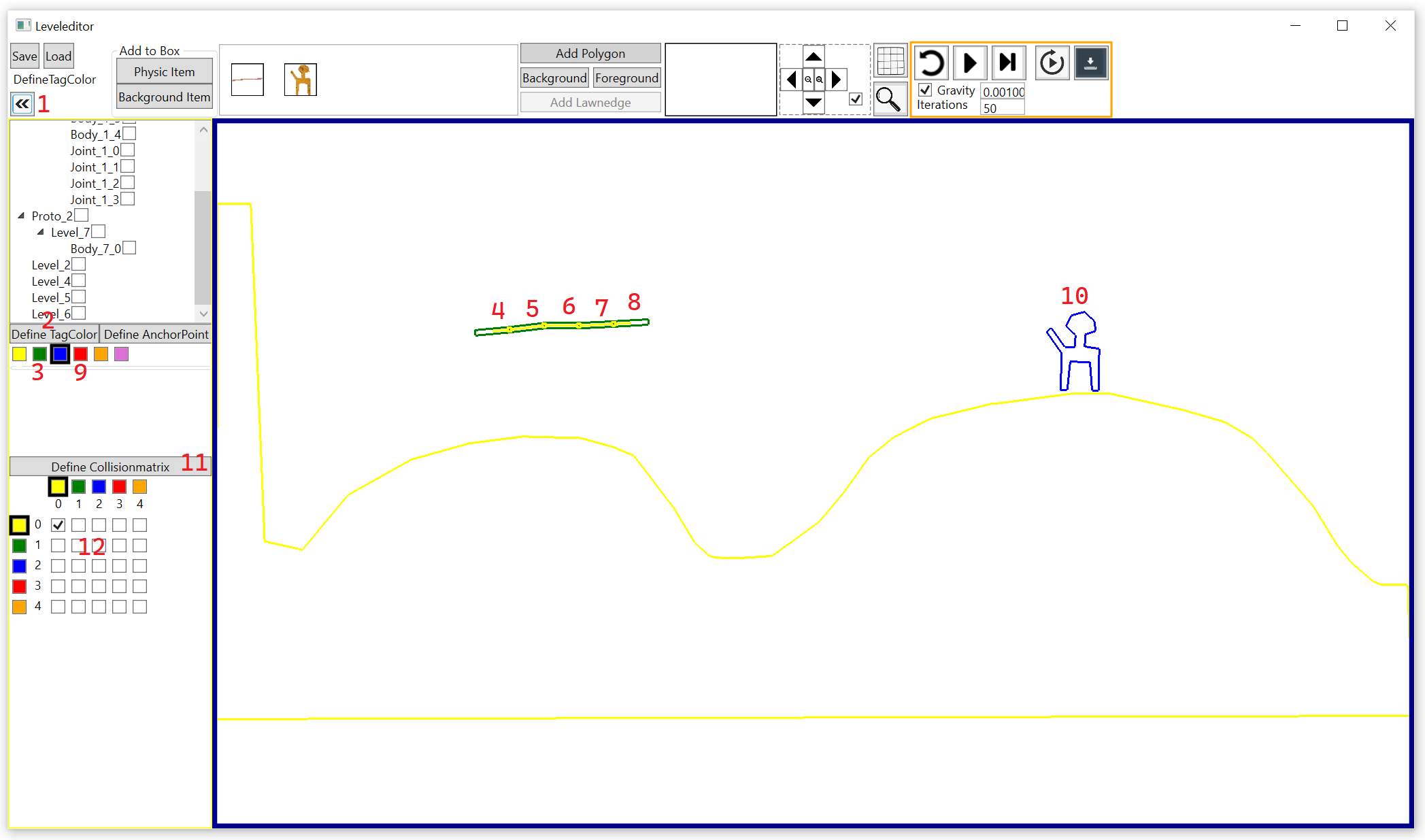
Click on the arrow-button(1) below the save button to open the tag-menue on the left side. Click now on the "Define TagColor"-Button (2) to show from all objects his tag color. Click on the green rectangle below (3) and then on all rectangles from the stick (4,5,6,7,8) to make the rectangles green. After that click on the blue rectangle (9) and then on the stone-man (10). If you click on "Define Collisionmatrix" (11) then you can define which object can collide with which other object. For this matrix you can also define a collision-matrix-color by clicking on the rectangles from the matrix and the checkboxes (12) from the matrix say then, which color collides with wich other color.
We have now defined the following colors: Yellow (TagColor=0) → Groundpolygon Green (TagColor=1) → Stick-Rectangles Blue (TagColor=2) → Stone-Man-Polygon
Save again the StickPlant.txt and go back to the viewmodel. We now add the logic for the collision-handling:
class ViewModel
{
	private bool stickIsTouchingTheFigure = false;

	public ViewModel(GraphicPanel2D panel)
	{
		...
		this.simulator.CollisonOccured += Simulator_CollisonOccured;
	}

	private void Simulator_CollisonOccured(PhysicScene sender, PublicRigidBodyCollision[] collisions)
	{
		foreach (var collision in collisions)
		{
			byte color1 = this.simulator.GetTagDataFromBody(collision.Body1).Color;
			byte color2 = this.simulator.GetTagDataFromBody(collision.Body2).Color;

			//Color-Values:
			//0 = Ground
			//1 = Stick
			//2 = Stoneman

			this.stickIsTouchingTheFigure = (color1 == 1 && color2 == 2) || (color1 == 2 && color2 == 1);
		}
	}
}
The bool-variable stickIsTouchingTheFigure is now updated every timer-tick and it indicates, if the stick is touching the stone man.
Handle collisions by tag name
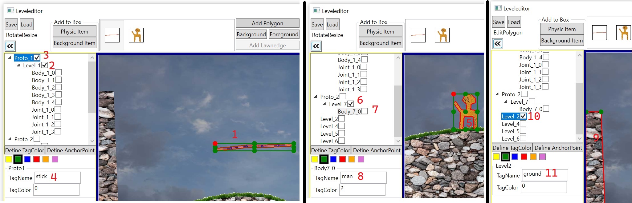
We can also use the tag-name for handling collisions. Go again in the Leveleditor.exe and Click on the stick (1) and you see, that the checkbox vom Level_1 (2) is selected, which shows, that the Level1-object (our stick) is selected. Click on the parent node (3) and now you can define the tagName (4) with value "stick". Do this also for the stone man by clicking on the man (5) and then on Proto_2 or Body_7_0 (7) where you can add a tagName (8) with value "man". The same is done with the ground-polygon. Click on it (9), select Level_2 (10) and define the tagName "ground" (11).
There are now two ways to handle the collisions between two objects. Way 1 is using the tag color and way 2 is using the tag name.
private void Simulator_CollisonOccured(PhysicScene sender, PublicRigidBodyCollision[] collisions)
{
	foreach (var collision in collisions)
	{
		//Way 1 for collisionhandling: Use the tagColor
		byte color1 = this.simulator.GetTagDataFromBody(collision.Body1).Color;
		byte color2 = this.simulator.GetTagDataFromBody(collision.Body2).Color;

		//Color-Values:
		//0 = Ground
		//1 = Stick
		//2 = Stoneman

		bool stickIsTouchingGround1 = (color1 == 0 && color2 == 1) || (color1 == 1 && color2 == 0);
		this.stickIsTouchingTheFigure = (color1 == 1 && color2 == 2) || (color1 == 2 && color2 == 1);


		//Way 2 for collisionhandling: Use the tagName
		string name1 = this.simulator.GetTagDataFromBody(collision.Body1).Names.FirstOrDefault();
		string name2 = this.simulator.GetTagDataFromBody(collision.Body2).Names.FirstOrDefault();

		bool stickIsTouchingGround2 = (name1 == "ground" && name2 == "stick") || (name1 == "stick" && name2 == "ground");
	}
}
Step 1.4 - camera tracking
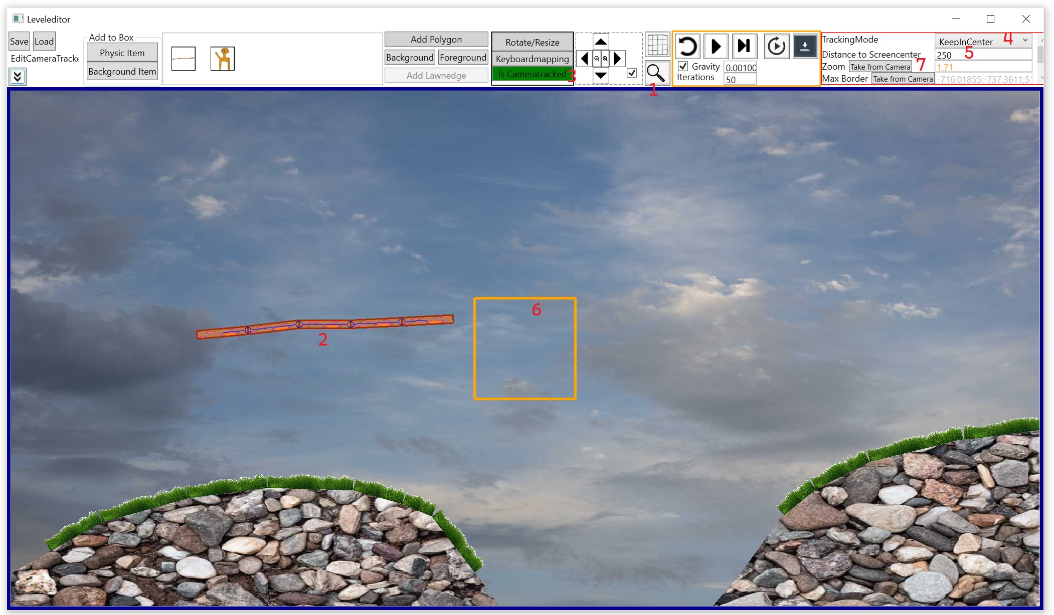
We want, that the camera is following the stick. To do so go to the Leveleditor.exe and click on the magnifying glass (1) and zoom in with the mouse wheel by holding the mouse in the yellow rectangle at the right bottom corner. After that click on the stick-object (2) and then on the "Is Cameratracked"-Button (3). The button becomes green now which shows, that the current selected item will now control the camera. Select as tracking mode "KeepInCenter" (4) and use 250 for "Distance to Screencenter" (5). The camera will now keep the center from the stick in the orange rectangle (6). Press also on the "Take from Camera" (7) button to tell the camera tracker which zoom should be used. It will use the zoom, which you are seeing in the editor at the moment.
If you now start the JumpingStick-project, then you will see, that the camera will now follow the stick.
If you don't want to use the camera tracker then select again the strick-object and press the "Is Cameratracked"-Button to remove the green color from this button.
Exampleproject 2 - Gripper
Step 2.1 - Define the levelfile "Gripper.txt"
This project shows how to simulate a gripper where WPF is used for graphic output. We need at first the definition of the physic model by using the Leveleditor.exe
Click on "Physic Item" (1) and then on "Add Rectangle" (2) and define the first rectangle (3), which is the rail from our gripper. Add a second rectangle (4) which is the suspension for the gripper. We now want to connect the two rectangles. The suspension-rectangle (4) should only move left and right but not falling down because the rail-rectangle (3) is holding it. To do so click on "Add Prismatic Joint" (5) and then at first on the rail-rectangle (3) and after that on the suspension-rectangle (4). Hold now the shift-key pressed to show the blue anchor-points and click on the left middle point (6). This point defines the direction from our rail (blue line). Release the shift-key and click at next on the top center point from the suspension-rectangle (7). The prismatic joint will now keep the anchorpoint from the suspension-rectangle on the blue-line from the rail-rectangle. The prismatic joint is now visulisized with the blue line (8).
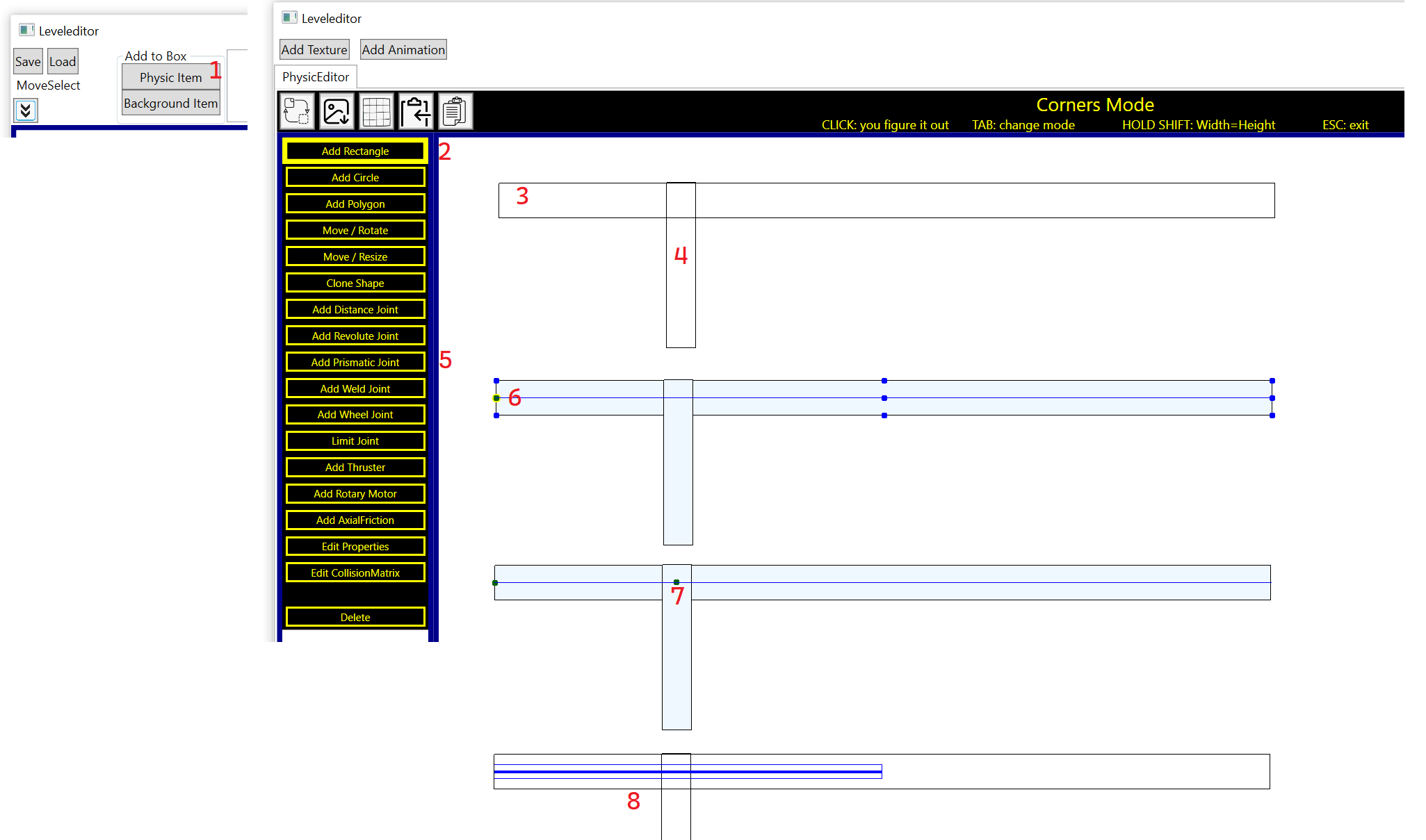
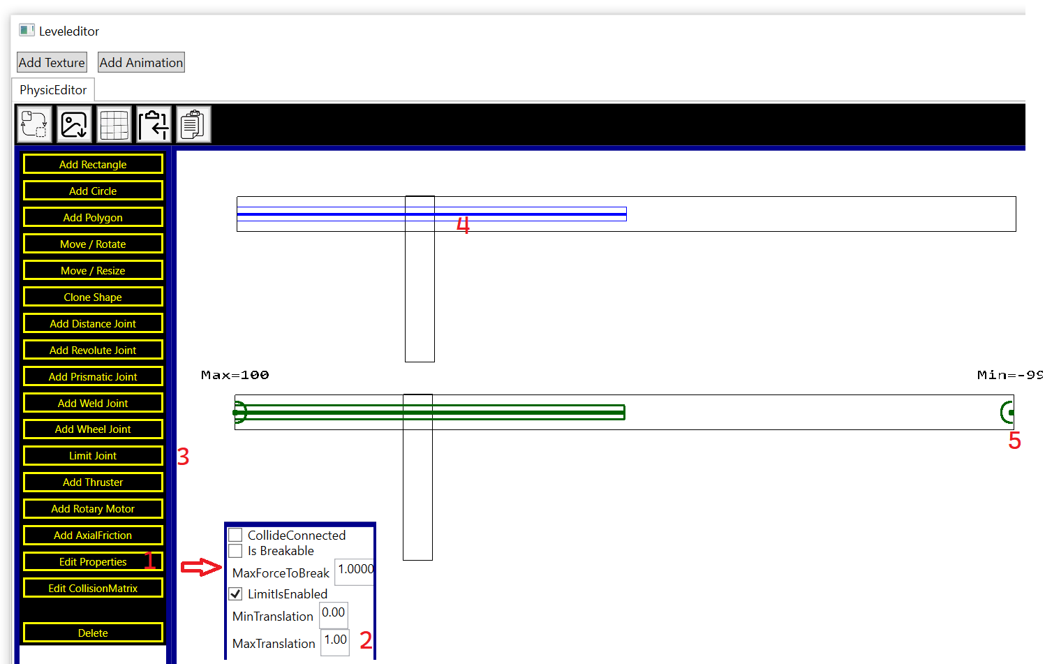
At next we want to define how far left and right is the suspension-rectangle allowed to go. Click on "Edit Properties" (1) and then hold shift and click on the prismatic joint. Change the MaxTranslation-value (2) to 1. This is necessary otherwise because the max-point is outside the visible area of the screen and can't be moved by mouse. Click on "Limit Joint" (3) and then again on the prismatic joint (4) and now move the min-point (5) to the right side from the rail-rectangle. The suspension can now move only between the min- and max-point.
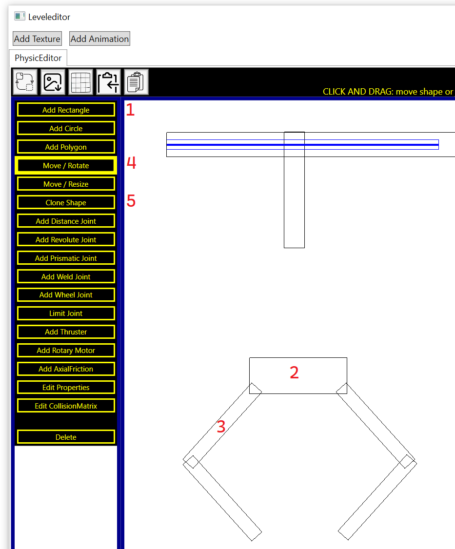
The next step is to create five rectangles for the gripper. Use for this the "Add Rectangle"-Function (2). For the small rectangles (3) you can at first create a horizontal rectangle and then rotatate it with the "Move / Rotate"-Function (4) by using the mouse wheel. If you hold shift durring scrolling, then you rotate in bigger steps. This is usefull, if you want to mirror the gripper-arms.
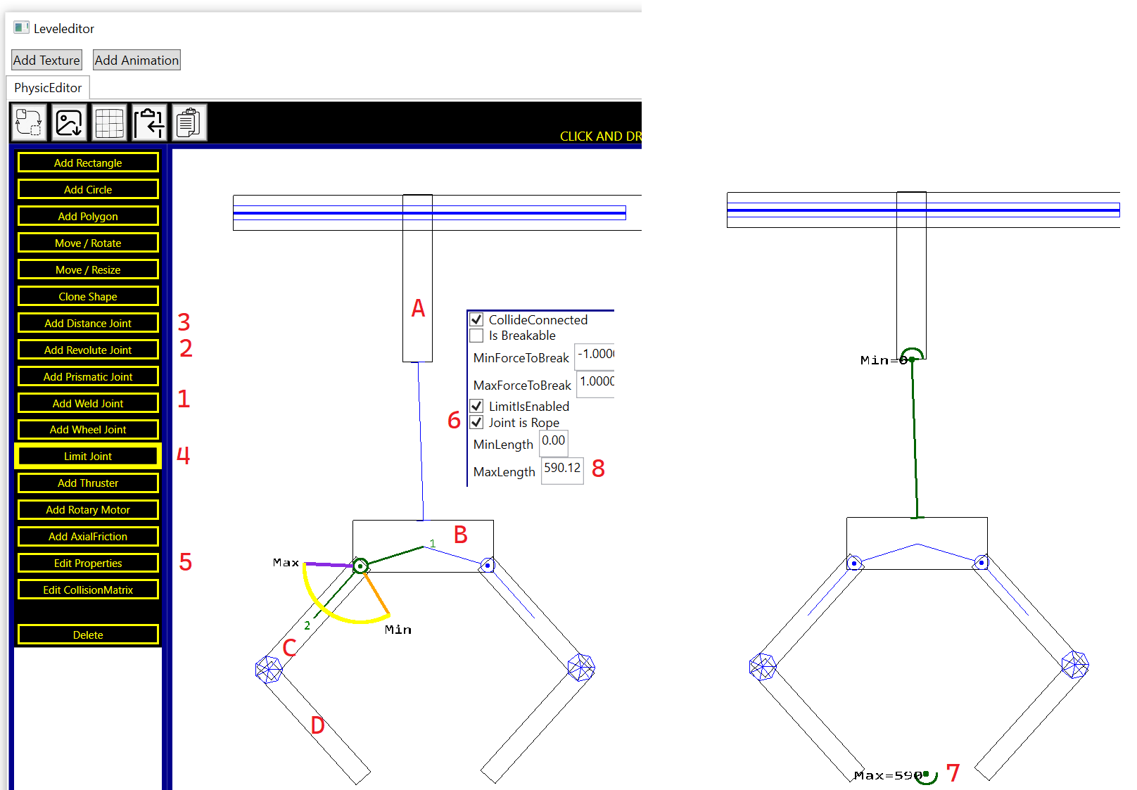
We now need joints for the gripper. Click on "Add Weld Joint" (1) and then at rectangle C and after that on rectangle D. Move the mouse to a point, where both rectangles overlapp and use this point to define for both rectangles the anchorpoint. The weld-joint will press the anchorpoints from the two rectangles together.
Click now on "Add Revolute Joint" (2) and then on rectangle B and then on rectangle C. Use again a point, which is inside from both rectangles and use this point as anchorpoint. If you click on "Limit Joint" (4) and then on the revolute joint, then your min-max-limits should look like in the picture. The green arm 2 is only allowed to move in the yellow circle arc.
At next we want to use a rope between rectangle A and B. Click on "Add Distance Joint" (3) and then on A and B. Hold shift to show the anchor-helper-points and place the anchorpoint in the bottom middle from rectangle A and in the top middle of rectangle B. Click on "Edit Properties" (5) and then on the distance joint and enable the "Joint is Rope"-checkbox (6). Otherwise the distance-joint will act like a stick, which can change his length. Click on "Limit Joint" (4) and then on the distance-joint and move the max-point (7) below to define have far the gripper can move downwards. You see this number also in the edit-settings (8).
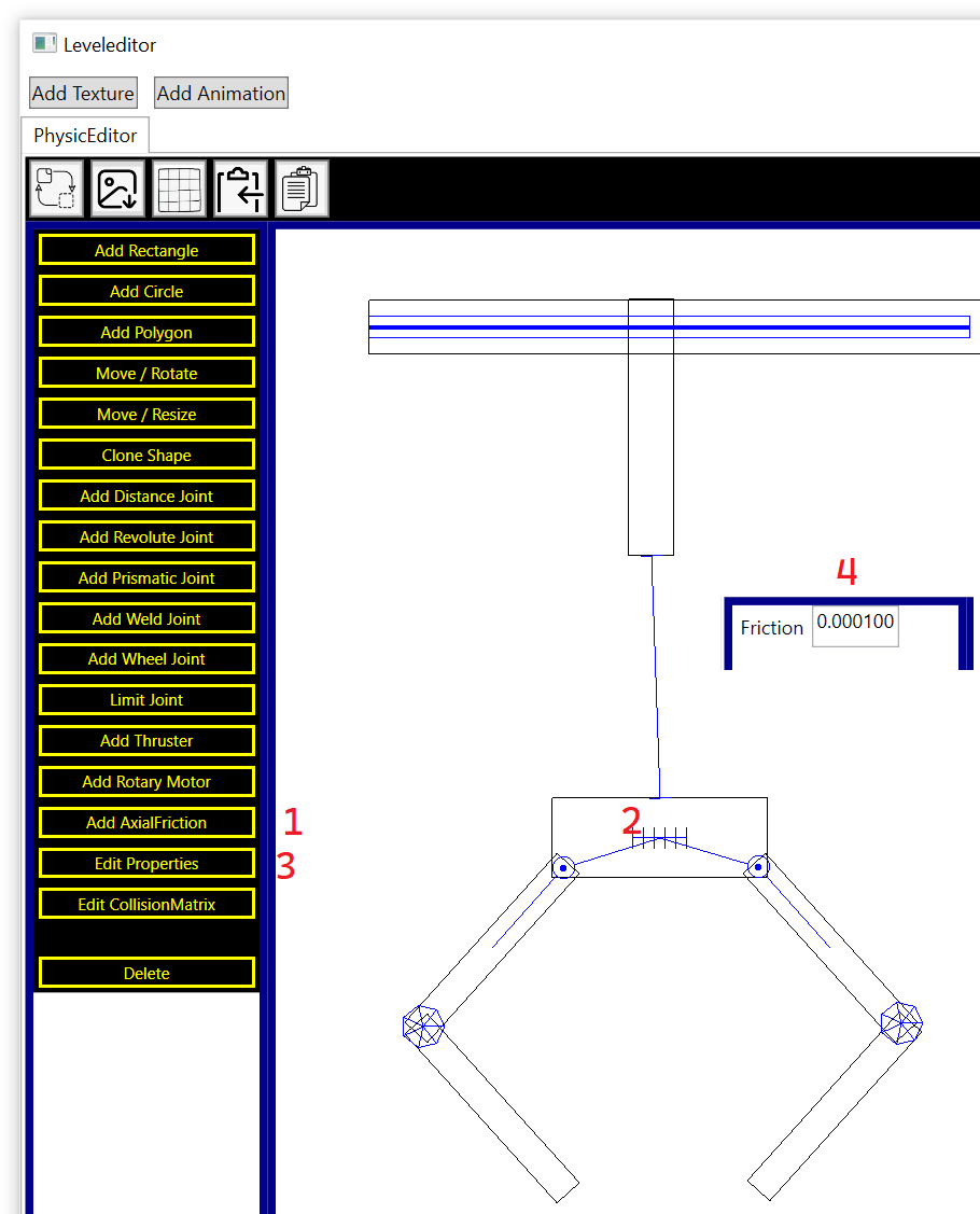
We need for the gripper also a little bit friction otherwise the gripper will swing to far to the left and right and it becomes hard to control. Click on "Add AxialFriction" (1) and then on rectangle 2. Hold shift and place the anchorpoint at the center. Hold shift again and oriented the direction from the friction-joint in horizontal direction. Click on "Edit Properties" (3) and use 0.0001 as friction value (4). This value was determined by trial and error.
It is necessary that the rail-rectangle is a fixed object. Click on "Edit Properties" and then on the rail-rectangle to change the mass-type to infinity.
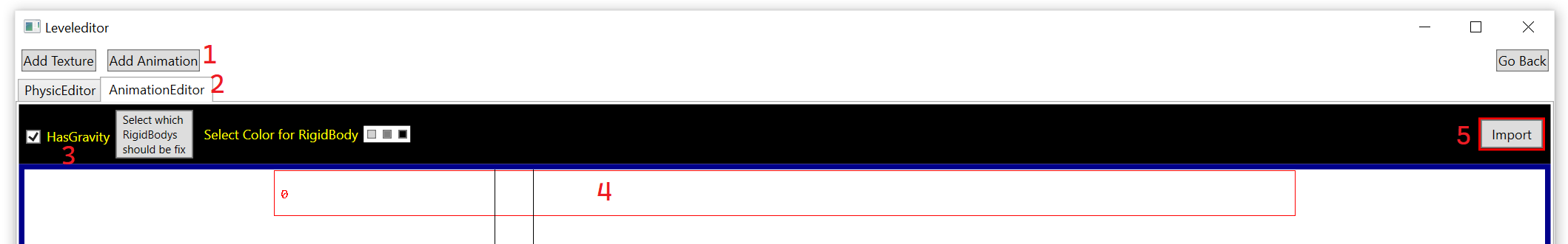
After that we now want to define the movement from the gripper. Click on "Add Animation" (1), go to the AnimationEditor-tab (2) and then activate the HasGravity-checkbox (3). You see, that the rail-rectangle (4) has a red border. This indicates, that this rectangle has a infinity mass (not moveable). Click on Import (5) now.
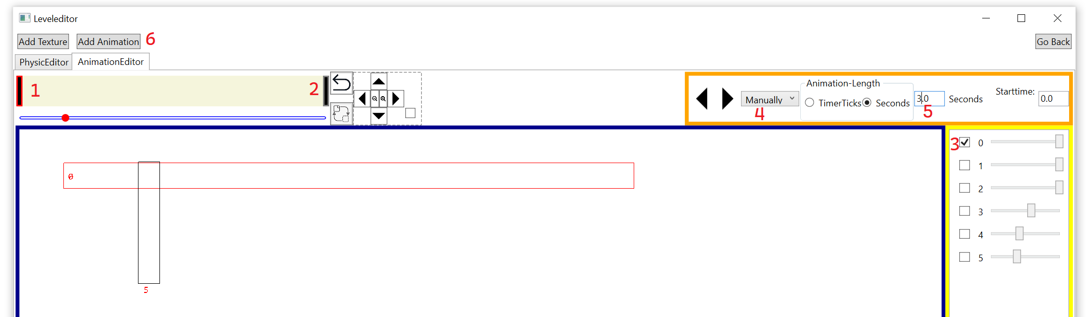
Right-click on the yellow area (1) to create a new key frame and then move this frame to the left by left-clicking it. Create a second key frame and move it to the right (2). Click on the first key frame and uncheck all checkboxes except the top one. This checkboxes indicates, which joints a controlled from this animation. Each joint can only be controlled by one animation. Define for both keyframes that at animation start the gripper starts at left (3) and at animation end on the right side. Use a manually animation (4) and increase the durration from the animation to 3 seconds (5).
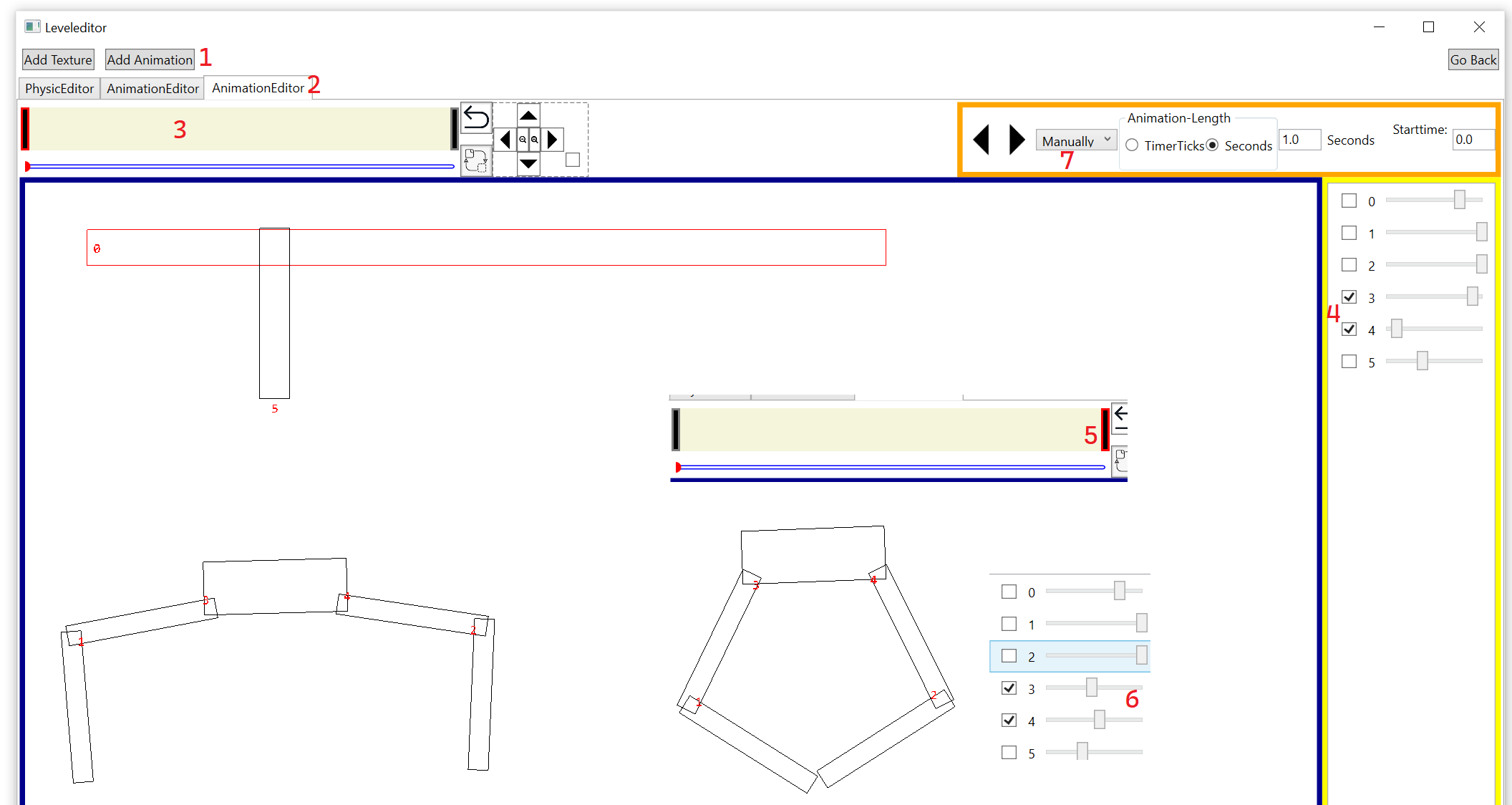
For the other joints we need a separat animation. Click again on "Add Animation" (1), open the second animation-tab (2) and then again on "HasGravity" and "Import". Add again two key frames (3) and activate the left key frame. Here we only want to animate the revolute joints. This two joints has the indizes 3 and 4. So only activate the checkbox from this two joints (4) to tell, that this animation-tab will only affect this two joints. For the left key frame the gripper is open and for the right key frame (5) the gripper is closed (6). We use again a manually animation-type (7).
The last animation will control the rope-length. Click on "Add Animation" (1), open the third animation (2), set "HasGravity" and click on "Import". Add two keyframes (3) and activate only the last checkbox (4) to tell, that this animation will only control the distance joint. At animation-start the gripper starts on top and at the end below. We need again the manually (5) animation and use a durration of 2 seconds (6).
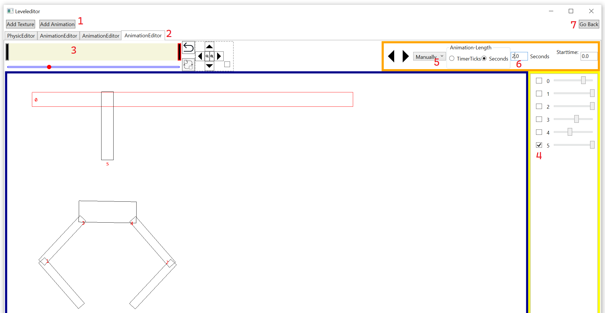
We are now finish with the definition of the gripper. Click on "Go Back" (7).
The item box contains now the gripper. Click on it (1) and place it in the level (2) by left clicking and then press esc to leave the AddItem-state. Select the gripper with the mouse (2) and click on Keyboardmapping (3) and then on "Add Entry" (4) and use "Q" (5) for the "Animation Backward 0" (6). Do this also for all the other animations:
- Q,A → Controls the left/right-position from the gripper
- W,S → Controls the open/close-position from the gripper
- E,D → Controls the rope-length from the gripper
You can now test the gripper by pressing on the simulation-button (7) and then press Q,A,W,S,E,D and see how the gripper is moving.
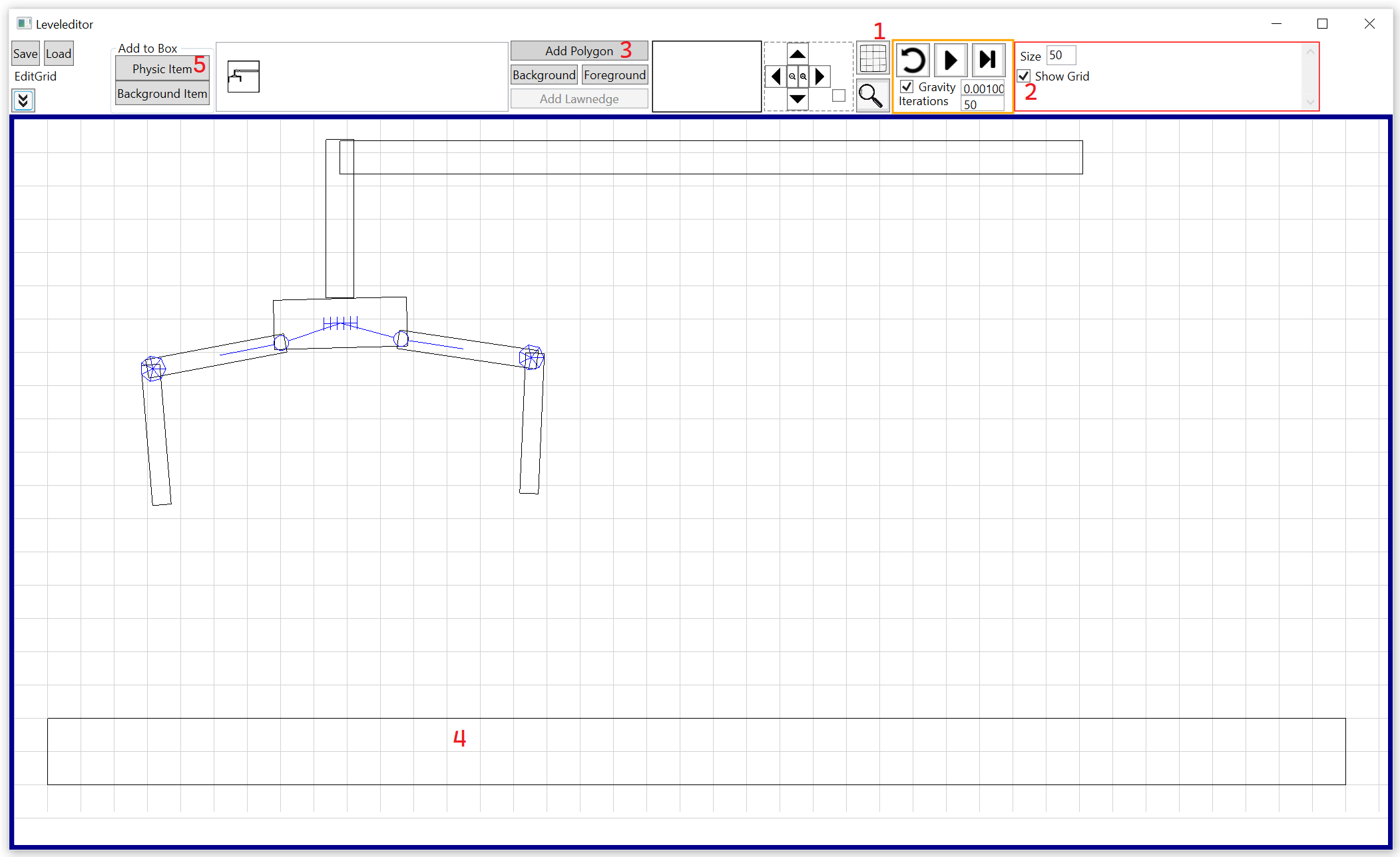
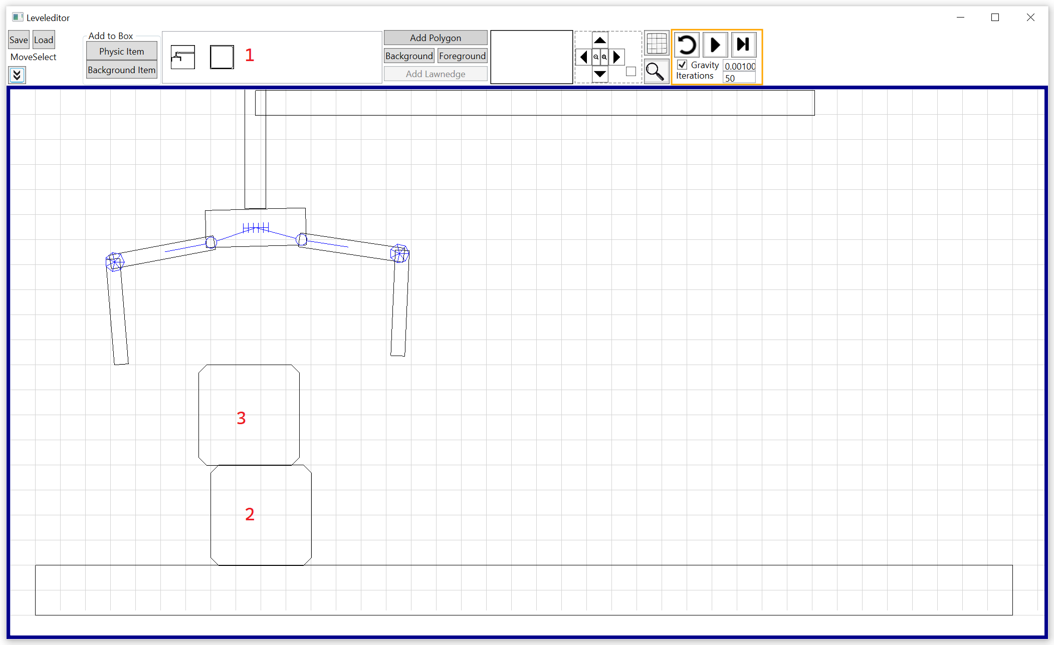
We need at next a ground. The make the ground straight we activate the grid-mode (1) / (2) and add now a polygon (3) which looks like a rectangle (4).
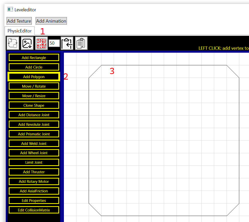
We now want some objects which can be used from the gripper. To do so click on "Physic Item" (5) and then active the grid mode also in the item editor (1) and create a polygon (2), which looks like this in the image (3):
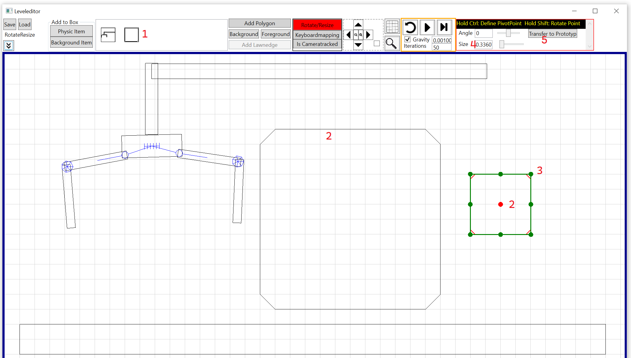
The box apears now in the item-box (1) and if you place the box in the level (2) then you see that the size is very big. Select the box, hold shift and select the middle point (2)
to define his pivot point. Now grap on of his corners (3) and move it to scale the box down. You see, that his size is changing (4). If you click "Transfer to Prototyp" (5) then
all new created boxes from the item-box will now have the small size.
Place now two boxes (1) to build a stack (2) and (3).
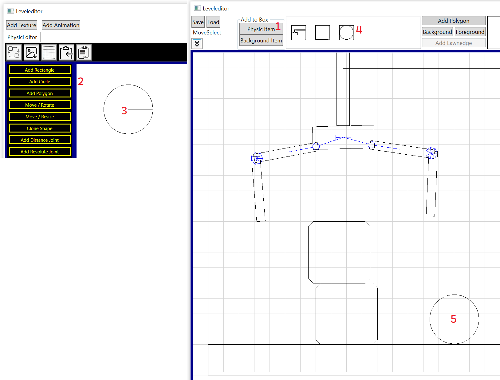
The second object should be a ball. Click on "Phyisc Item" (1) and then on "Add Circle" (2). Change the size with the scroll-wheel and place the circle in the item-editor (3).
Click "Go Back" and then use the item (4) and place it in the level (5).
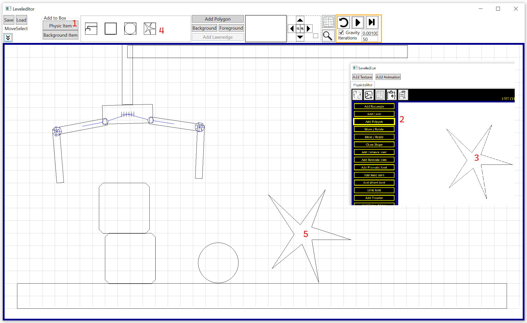
The last object should be a star. Click on "Phyic Item" (1), then on "Add Polygon" (2), define the star (3), "GoBack", take the star from the item-box (4) and place it in the level (5).
Save now the level as Gripper.txt.
Step 2.2 - Use the "Gripper.txt"-File in code
For this step: Open the Gripper-project from here: https://github.com/XMAMan/RigidBodyPhysicsExamples/tree/master/Source/PhysicExamples.sln
This project was created by using a WPF.NET 8.0-projecttype and its using only the nuget "XMAMan.PhysicEngine". For the graphic output the WPF-canvas-element is used.
The MainWindow.xaml contains a canvas with name "canvas".
<Window Title="Jumping Stick" Height="450" Width="800" Loaded="Window_Loaded">
    <Grid>
		<Canvas x:Name="canvas"/>
		<StackPanel>
			<Label Content="Q,A = move gripper left/right"/>
			<Label Content="W,S = open/close gripper"/>
			<Label Content="E,D = move gripper up/down"/>
		</StackPanel>
	</Grid>
</Window>
In the code-behind from the MainWindow the ViewModel is created and the key-press-events are used:
public partial class MainWindow : Window
{
    public MainWindow()
    {
        InitializeComponent();

        this.DataContext = new ViewModel(this.canvas);
    }

    private void Window_Loaded(object sender, RoutedEventArgs e)
    {
        var window = Window.GetWindow(this);

        window.KeyDown += (this.DataContext as ViewModel).HandleKeyDown;
        window.KeyUp += (this.DataContext as ViewModel).HandleKeyUp;
    }
}
The ViewModel contains a GameSimulator-object which moves the objects in the timer-tick-handler.
class ViewModel
{
    private GameSimulator simulator;                            //Comes from XMAMan.PhysicEngine
    private System.Windows.Threading.DispatcherTimer timer;
    private System.Windows.Controls.Canvas canvas;
    private List<IMoveable> moveables = new List<IMoveable>();

	public ViewModel(System.Windows.Controls.Canvas canvas)
	{
		this.canvas = canvas;

		//This is needet to update the camera position/zoom when the window is resized
		this.canvas.SizeChanged += (s, e) =>
		{
			this.simulator?.PanelSizeChangedHandler((int)canvas.ActualWidth, (int)canvas.ActualHeight);
		};

		this.timer = new System.Windows.Threading.DispatcherTimer();
		this.timer.Interval = new TimeSpan(0, 0, 0, 0, 30);//30 ms
		this.timer.Tick += Timer_Tick;

		Load();

		this.timer.Start();
	}

	private void Timer_Tick(object? sender, EventArgs e)
	{
		//Move all objects
		this.simulator.MoveOneStep((float)this.timer.Interval.TotalMilliseconds);

		//Update objectpositions from UI-Elements
		foreach (var moveable in this.moveables)
		{
			moveable.Move();
		}

		//Update camera-Position from Canvas
		this.canvas.RenderTransform = GetCameraTransform();
	}

	public void HandleKeyDown(object sender, System.Windows.Input.KeyEventArgs e)
	{
		if (e.IsRepeat) return; //So verhindere ich, dass bei gedrückter Taste der Handler mehrmals aufgerufen wird

		this.simulator.HandleKeyDown(e.Key);
	}

	public void HandleKeyUp(object sender, System.Windows.Input.KeyEventArgs e)
	{
		if (e.IsRepeat) return;

		this.simulator.HandleKeyUp(e.Key);
	}
}
A MoveableBody has a reference to a Shape-object, which is shown from the canvas. The IPublicRigidBody-object is a reference to a rigid body from the physic simulation. This object is used to get the current position and oriantation from a rectangle, circle or polygon by using the Center- and Angle-property.
class MoveableBody : IMoveable
{
    private Shape uiElement;
    private IPublicRigidBody physicObject;
    private Vec2D centerOfMass;

    public MoveableBody(Shape uiElement, IPublicRigidBody physicObject, Vec2D localCenterOfMass)
    {
        this.uiElement = uiElement;
        this.physicObject = physicObject;
        this.centerOfMass = localCenterOfMass; //points from (0,0) left top corner of a object to his center of Mass
    }

    public void Move()
    {
        TransformGroup transforms = new TransformGroup();
        transforms.Children.Add(new TranslateTransform(-this.centerOfMass.X, -this.centerOfMass.Y)); //Move center to origin
        transforms.Children.Add(new RotateTransform(this.physicObject.Angle / (float)Math.PI * 180)); //Rotate around center. Convert Angle in degrees

        transforms.Children.Add(new TranslateTransform(this.physicObject.Center.X, this.physicObject.Center.Y)); //Move origin to physic-center

        this.uiElement.RenderTransform = transforms;
    }
}
The Load-Method is called in the constructor from the ViewModel. With the GetAllBodiesOfType-method you get access to all rigid bodys from the scene. There are 3 subtypes: IPublicRigidRectangle, IPublicRigidCircle and IPublicRigidPolygon. The distance-joints from the scene can be accessed with GetAllJointsOfType<IPublicDistanceJoint>().
private void Load()
{
    this.simulator = new GameSimulator(DataFolder + "Gripper.txt", (float)this.timer.Interval.TotalMilliseconds);

    foreach (var physicRec in this.simulator.GetAllBodiesOfType<IPublicRigidRectangle>())
    {
        System.Windows.Shapes.Rectangle uiRect = new System.Windows.Shapes.Rectangle();
        uiRect.Width = physicRec.Size.X;
        uiRect.Height = physicRec.Size.Y;
        uiRect.Fill = System.Windows.Media.Brushes.Red;
        uiRect.Stroke = System.Windows.Media.Brushes.Black;

        this.canvas.Children.Add(uiRect);

        this.moveables.Add(new MoveableBody(uiRect, physicRec, new Vec2D(physicRec.Size.X / 2, physicRec.Size.Y / 2)));
    }

    foreach (var physicCircle in this.simulator.GetAllBodiesOfType<IPublicRigidCircle>())
    {
        System.Windows.Shapes.Ellipse uiCircle = new System.Windows.Shapes.Ellipse();
        uiCircle.Width = physicCircle.Radius * 2;
        uiCircle.Height = physicCircle.Radius * 2;
        uiCircle.Fill = System.Windows.Media.Brushes.Blue;
        uiCircle.Stroke = System.Windows.Media.Brushes.Black;

        this.canvas.Children.Add(uiCircle);

        this.moveables.Add(new MoveableBody(uiCircle, physicCircle, new Vec2D(physicCircle.Radius, physicCircle.Radius)));
    }

    foreach (var physicPolygon in this.simulator.GetAllBodiesOfType<IPublicRigidPolygon>())
    {
        System.Windows.Shapes.Polygon uiPolygon = new System.Windows.Shapes.Polygon();

        float minX = physicPolygon.Vertex.Min(x => x.X);
        float minY = physicPolygon.Vertex.Min(x => x.Y);

        uiPolygon.Points.AddRange(physicPolygon.Vertex.Select(p => new System.Windows.Point(p.X - minX, p.Y - minY))); //Point (0,0) is the left top corner from the polygon
        uiPolygon.Fill = System.Windows.Media.Brushes.Green;
        uiPolygon.Stroke = System.Windows.Media.Brushes.Black;

        this.canvas.Children.Add(uiPolygon);

        this.moveables.Add(new MoveableBody(uiPolygon, physicPolygon, physicPolygon.Center - new Vec2D(minX, minY)));
    }

    foreach (var distanceJoint in this.simulator.GetAllJointsOfType<IPublicDistanceJoint>())
    {
        System.Windows.Shapes.Line uiLine = new System.Windows.Shapes.Line();
        uiLine.Stroke = System.Windows.Media.Brushes.Black;
        uiLine.StrokeThickness = 2;

        this.canvas.Children.Add(uiLine);
        this.moveables.Add(new MoveableDistanceJoint(uiLine, distanceJoint));
    }
}
| Product | Versions Compatible and additional computed target framework versions. |
|---|---|
| .NET | net8.0-windows7.0 is compatible. net9.0-windows was computed. net10.0-windows was computed. |
-
net8.0-windows7.0
- XMAMan.GraphicEngine2D (>= 0.0.1)
NuGet packages
This package is not used by any NuGet packages.
GitHub repositories
This package is not used by any popular GitHub repositories.
make GraphicPanel2D-property from DrawingPanel public